|
Retrospective Computed Tomography Scan Analysis of Percutaneously Inserted Pedicle Screws for Posterior Transpedicular Stabilization of the Thoracic and Lumbar Spine
Accuracy and Complication Rates
Darryl A. Raley, MBBS, BSc * Ralph J. Mobbs , BSc, MBBS, MS, FRACS* †
Study Design. Retrospective clinical data analysis.
Objective. To investigate the misplacement rate and related
clinical complications of percutaneous pedicle screw insertion in
the thoracic and lumbar spine.
Summary of Background Data. Percutaneous insertion of
cannulated pedicle screws has been developed as a minimally
invasive alternative to the open technique during instrumented
fusion procedures of the thoraco-lumbar spine. The reported rate
of screw misplacement using open techniques is well described,
however data is lacking on the exact failure rate of the percutaneous
technique.
Methods. A total of 424 percutaneously inserted pedicle screws
from 2007 to 2010 were analyzed in 88 patients, from a single
surgeon series (RJM). Axial reformatted computer tomographic
images were examined by 2 independent observers and individual
and consensus interpretation was obtained for each screw position. A
simple grading system was used for assessment of screw accuracy—
Grade 0: screw within cortex of pedicle; Grade 1: screw thread
breach of wall of pedicle < 2 mm; Grade 2: signifi cant breach > 2 mm
with no neurological compromise; Grade 3: complication including
pedicle fracture, anterior breach with neuro-vascular compromise,
and lateral or medial breach with neurological sequelae.
Results. The indications for percutaneous pedicle screw insertion
include: degenerative (78%), trauma (13%), tumour (8%), and infection (1%). Pedicle screws were inserted into level T4 to S1. The
most common levels performed include L4 and L5 with the most
common indication for surgery being an L4/5 spondylolisthesis. 383
out of 424 screws (90.3%) were placed in the cortical shell of the
pedicle (Grade 0). Forty-one screws (9.7%) were misplaced from
T4 to S1. Of these, the majority were Grade 1 pedicle violations
(24 screws; 5.7%), with 15 Grade 2 violations (3.5%) and 2 Grade
3 violations (0.5%). Of the 2 Grade 3 pedicle violations, both were
pedicle fractures but only 1 had associated neurological defi cit (L4
radiculopathy postoperatively).
Conclusion. Percutaneous insertion of cannulated pedicle screws
in the thoracic and lumbar spine is an acceptable technique with
a low complication rate in experienced hands. The overall rate of
perforation is below the higher rates reported in the literature for
the open technique. Complication rates including pedicle fracture
were low.
Key words: pedicle screw fi xation , posterior stabilization ,
computer tomography , minimally invasive surgery , lumbar spine .
Spine 2012 ; 37 : 1092 – 1100
From the * Prince of Wales Hospital, Randwick, Sydney, Australia ; and
† Sydney Spine Clinic, Sydney, Australia .
Acknowledgment date: April 8, 2011. First revision date: September 29,
2011. Acceptance date: October 1, 2011.
The manuscript submitted does not contain information about medical
device(s)/drug(s).
No funds were received in support of this work. One or more of the author(s) has/have received or will receive benefi ts for personal or professional use from a commercial party related directly or indirectly to the subject of this manuscript: e.g. , honoraria, gifts, consultancies, royalties, stocks, stock options, decision making position.
Address correspondence and reprint requests to Dr. Darryl Raley, MBBS, BSc,
9 Clematis Close, Cherrybrook, Sydney, NSW 2126; E-mail: darryl.raley@gmail.com
DOI: 10.1097/BRS.0b013e31823c80d8
Spinal fusion using pedicle screws is a widely accepted
method for the management of a variety of spinal conditions
requiring stabilization. Traditional open techniques
for insertion of screws are associated with extensive
blood loss, lengthy hospital stays, and signifi cant costs.1
Minimally invasive techniques use small incisions and small
muscle splitting approaches, and are associated with less
blood loss, less soft tissue trauma, and less postoperative pain
than traditional open techniques.2–6 Many studies have investigated
the accuracy of screw placement by a conventional
open approach using simple radiograph, computed tomographic
(CT) scan, or magnetic resonance imaging,7–12 with
reported rates of screw misplacement up to 40%. 7 However,
there is a paucity of data on the exact failure rate of the percutaneous
technique. In this article, we focus on the accuracy
by 1 surgeon of purcutaneous pedicle screw placement
and introduce a simple grading system for CT evaluation of
pedicle screw placement. The purpose of our study was to defi ne the incidence of pedicle misplacement and compare it
with published data on open and percutaneous pedicle placement
techniques.
MATERIALS AND METHODS
Between 2007 and mid-2010, 88 consecutive patients
(47 men and 41 women) were analyzed after external transpedicular
screw fi xation of the thoracic, lumbar and sacral
spine (from T4 to S1). All patients had a CT performed
within 24 hours of surgery and fi lms entered into a database
for review. The age range of the patients was 9 to 85 years
(mean, 63 yr). The operations were performed at The Prince
of Wales Public and Private Hospitals, Sydney, Australia.
Surgical Procedure
All surgical procedures were performed by a single spine
surgeon (RJM). A total of 424 screws were implanted in 88
patients undergoing percutaneous thoracolumbar or lumbosacral
stabilization using the Serengeti spinal system (K2M,
Leesburg, VA, USA). Percutaneous pedicle screws ranged in
diameter from 4.5 to 7.5 mm and were inserted in accordance
with the technique described by Wiesner et al.13
A brief description of this technique follows (Figures 1 , 2 ):
- The image intensifi er (II) is placed in the AP position. The
spinous process should be midline between the pedicles
to ensure a direct AP projection ( Figure 2 A).
- The position of the lateral aspect of the pedicle is marked on
the skin. Depending upon the depth of the tissue between
skin and pedicle, the skin incision should be made lateral
( Figure 1 A) so that appropriate angulation of the Jamshidi
needle can be made when inserting into the pedicle.
- The Jamshidi needle is placed through the skin incision
and “docked” onto the lateral aspect of the pedicle
(Figures 1 A, 2 ). This is called the “3 o-clock” position.
- The Jamshidi needle is advanced 20 to 25 mm into the
pedicle through the cortical bone, making sure the needle
remains lateral to the medial pedicle wall (Figures 1 A, 2 ).
A second Jamshidi needle can then be placed on the contralateral
side in a similar fashion.
- The II is then positioned in the lateral plane. The Jamshidi
needle should now be in the vertebral body, and therefore
“safe” with no risk of medial pedicle breach (Figures 1 A, 2 ).
- The stylet is then removed and a Kirschner (K)-wire is placed down the barrel of the Jamshidi needle. Once a
satisfactory penetration of the pedicle with the K-wire is
completed, the Jamshidi needle is removed, taking care
to maintain the position of the K-wire. A cannulated
scalpel is then passed over the K-wires to provide accurate
incisions that are long enough for the tissue guard.
- Tissue guards are then placed over the K-wires to perform
soft tissue dissection down to the level of the bone.
A pedicle screw tap is then placed down the trajectory
of the K-wire, through the pedicle into the trabecular
bone of the vertebral body, taking care the K-wire is not
moved during introduction ( Figure 2 ).
- The tap is then removed and the appropriate pedicle
screws (measurements based on preoperative CT scans)
are placed down the K-wire ( Figure 2 ), making sure not
to advance the K-wire beyond the anterior aspect of the
vertebral body. Confi rmation of pedicle screw placement
is achieved with II.
- The rods are then inserted via the pedicle screw incision
sites and join the pedicle screw heads. A dedicated reduction
device can be used with the retractor sleeves for
correction of a spondylolisthesis.
- The retractor sleeves are then removed
- All wounds are then closed via a standard method.
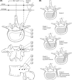
Figure 1. (A) Diagrams illustrating the
anatomical principles of percutaneous
pedicle screw insertion: views from top to
bottom: superior, posterior, lateral, superior.
First the initial skin incision is
made with the patients’ body habitus in
mind. Second, the Jamshidi needle is fi rst
‘‘docked’’ onto the lateral aspect of the
pedicle — ‘‘position 1’’ — on the anterior/
posterior image intensifi er (II) radiograph
projection. Third, the Jamshidi needle is
advanced 20 to 25 mm so that the needle
is beyond the medial border of the pedicle
and into the vertebral body – to ‘‘position
3.” Finally, the position is confi rmed by
lateral II radiograph projection before insertion
of the K-wire. (B) Grading system
for evaluation of screw position.
Postoperative CT was obtained for all patients to assess
implant position, using a GE 16 slice Brightspeed unit with
0.625 mm slices acquired in helical mode in a craniocaudal
direction.
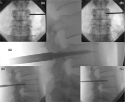
Figure 2. Percutaneous Technique (L4 Pedicle).
(A) Using AP x-ray, the Jamshidi needle
is ‘docked’ onto the facet/TP junction. (B)
The needle is advanced 20 to 25 mm making
sure that the tip of the Jamshidi is not beyond
the medial pedicle border. (C) Lateral
x-ray confi rms that the Jamshidi is within the
vertebral body. (D) Tapping the pedicle. (E)
Insertion of pedicle screw.
Evaluation of Screw Position
Two independent observers analyzed digital axial CT slices
of all instrumented pedicles, with individual and consensus
interpretation for each screw. A simple grading system
(Mobbs Raley) was devised for evaluation of screw position
( Figures 1 B, 6 ).
The grading system was devised to indicate accuracy of
placement (Grade 0, 1, 2) and a signifi cant complication with
the technique (Grade 3) that was likely to require revision
surgery ( Table 1 ).
The direction of the pedicle violations was noted, and
the degree of the screw malalignment in the axial plane was
measured. The transverse screw angle was determined by
measuring the angle between a line parallel to the vertebral
midline and a line through the center of the screw tract,
and was measured for all pedicles that showed a screw
displacement.
| TABLE 1. Grading System for Evaluation of
Screw Position |
| Grade 0 |
Screw within cortex of pedicle |
| Grade 1 |
Screw thread breach of wall of pedicle: ≤ 2 mm |
| Grade 2 |
Significant breach: > 2 mm. No neurological
compromise |
| Grade 3 |
Complication: pedicle fracture, anterior breach
with neuro-vascular compromise, lateral/medial
breach with neurological sequelae |
K-wire Complication
A serious potential complication can arise from insertion of
the K-wire beyond the anterior aspect of the vertebral body
( Figure 7 ). This can either occur from aggressive advancement
of the K-wire down the barrel of the Jamshidi, osteoporotic
bone with poor tactile feedback when inserting the
K-wire, or with the K-wire inadvertently moving distally
with advancement of the pedicle tap.
There are no reports in the literature that discuss complication
rates from anterior placement of a K-wire at the
time of percutaneous pedicle screw placement. All cases of
anterior placement of K-wires were prospectively recorded,
and any subsequent complications noted such as blood loss
or ileus.
Radiation Exposure
Mean operative time and mean fl uoroscopy time was
recorded for the fi rst and last 5 patients in the series receiving
single-level fusion (4 pedicle screws), to extrapolate surgeon
radiation exposure, and to demonstrate the learning curve
associated with the technique. In addition, mean radiation
exposure (mGy) to the last 5 patients receiving single-level
fusion was obtained from a standard measurement of output
from the C-arm of the image intensifi er. The C-arm was
in the source inferior position for all cases. Only single-shot
pulsed imaging was performed.
Statistical Analysis
The chi squared method and Fisher exact test (2-tail) was
used to determine signifi cant differences in the number of
screw malpositions, the direction of screw misplacement, and
corresponding angulation. In addition, because only a small
number of screws were placed at the thoracic levels, the pedicles
of T4 to T12 were combined and analyzed separately
as thoracic pedicles. Among the lumbar vertebrae, tests for
equal proportions were used to determine if there was a tendency
for lateral or medial pedicle violations and, for those
with a lateral pedicle violation, if this was due to incorrect
angle of insertion. The signifi cant difference level was set at
P < 0.05. Statistical analysis was performed using R-2.11.1
(R Foundation for Statistical Computing, Vienna, Austria).
RESULTS
A total of 424 percutaneously inserted pedicle screws were
analyzed in 88 patients, and 383 screws (90.3%) were placed
in the cortical shell of the pedicle (Grade 0). Only 41 screws
(9.7%) were misplaced from T4 to S1. Of these, the majority
were Grade 1 pedicle violations (24 screws; 5.7%), with 15
Grade 2 violations (3.5%) and 2 Grade 3 violations (0.5%;
Figure 3 ). There were 30 lateral and 11 medial pedicle cortex
violations ( Table 3 ). At the lumbar level there were signifi
cantly more lateral (n = 26) than medial (n = 7) cortical
violations ( P = 0.00094), whereas at the thoracic level there
was no difference.
The indications for screw insertion were predominantly
degenerative (n = 69, 78%), and included trauma (n = 11,
13%), tumor (n = 7, 8%), and infection (n = 1, 1%; Figure 4 ). The distribution of screw misplacements with respect to the
vertebral level is shown in Table 2 and graphically in Figure 5 .
There were no signifi cant differences within the lumbar vertebrae,
with failure rates between 4% (L2) and 16% (L3),
P = 0.6134. Combining thoracic levels T4 to T12, there
were no signifi cant differences compared with lumbar pedicle
screw misplacements (9.2% and 9.5%, respectively,
P = 0.8746). We found no correlation between the operated
level and screw malpositioning.
The transverse pedicle angle was measured for all misplaced
screws ( Table 2 ). Considering the direction of the
screw malalignment and the difference between the screw
and pedicle angle, 18 of the 41 pedicle violations (43.9%)
could be attributed to wrong angle of insertion. Of the lateral
cortical violations at the lumbar level (26 of 33 misplaced
screws), 13 (50%) could be attributed to incorrect angle of
insertion ( P = 0.8450).
There were 2 Grade 3 pedicle violations (patient 31 and
49, respectively, Table 2 ). One was a pedicle fracture without
neurovascular compromise; the other was a pedicle fracture
with L4 nerve injury (L4 radiculopathy postoperatively).
Both Grade 3 pedicle violations were performed early in the
series (within the initial 10 patients operated on).
There were 4 anterior K-wire perforations (0.9% of all
screws) during the course of the study period. One case was
because of advancement of the K-wire at the time of tapping
the pedicle, 2 cases were because of osteoporotic bone with
poor tactile feedback for the surgeon and 1 case of forceful
advancement of the K-wire with anterior puncture of the
vertebral body ( Figure 7 ). From the 4 cases identifi ed with
K-wire perforation, 1 patient had a small volume retroperitoneal
bleed and ileus treated conservatively. The other 3
patients had an uneventful recovery postoperatively.
Mean operative time was 238 minutes for the fi rst 5
patients, and 147 minutes for the last 5 patients receiving
single-level fusion (4 pedicle screws). The mean fl uoroscopy
time was 1.71 minutes for the fi rst 5 single-level cases (0.43
min/screw), and 0.76 minutes for the last 5 single-level cases
(0.11 min/screw). Mean maximum patient exposure for
these last 5 cases, measured from the output of the C-arm,
was 44.9 mGy (range 26.8–58.1 mGy).
DISCUSSION
The accuracy of pedicle screw placement using the traditional
open technique has been the subject of several imaging
studies. However, the reported misplacement rates have been
very different, ranging from 8% to 40%.7,14 This is partly
due to the lack of image guidance and the variation in pedicle
placement assessment methods including the defi nition of
misplacement.
Evaluation of percutaneous screw insertion for temporary
external fi xation (a diagnostic tool) with fl uoroscopic guidance
has been undertaken using a human cadaver model.13
The reported overall perforation rate of the dissected specimens
was 10% (mainly medial). In a separate study the same
authors evaluated screw position of percutaneous external
fi xation using axial CT images, with 51 patients and 408 pedicle screws.15 They reported a screw perforation rate of
6.6% (mainly medial and more often affecting the S1 pedicles).
Despite the screws used being noncannulated, this was
the fi rst study to analyze the accuracy of percutaneous transpedicular
screws. From recent publications on small series
of percutaneously inserted cannulated pedicle screws under
fl ouroscopic guidance,2,4,16–18 only 2 addressed the accuracy
of screw positioning. The smaller group was comprised of
only 3 patients with a single perforated screw.4 A somewhat
larger series (15 patients with a total of 60 screws),
reported an overall rate of screw perforation of 23% with
an incidence of severe frank pedicle penetration of 3.3% as
seen on axial images.18 The larger series to date reporting
results of percutaneous fi xation does not provide information
on screw placement. However, the reoperation rate
reported due to screw misplacement was 4% in that study
(2 of 49 patients).17
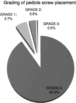
Figure 3. Pie chart showing the number of pedicle screws (%)
at each grade.
In our group of 88 patients with a total of 424 screws the
overall rate of screw perforation was 9.7% (41 screws) with
an incidence of severe frank pedicle penetration of 0.5% (2 of
424 screws) as seen on axial images. The incidence of screw misplacement in our series falls well within the reported rates
for the open technique, ranging from 8% to 40%,7,14 as well
as those reported for the percutanoues technique (6.6% to
10%, and up to 23%13,15,18). The neurological injury incidence
of 0.5% falls well below reported incidences ranging
from 2%19 to 5%, and even as high as 16.6%.7 Both Grade 3
pedicle violations occurred early in the series (within the fi rst
30 patients operated on), indicating a steep learning curve for
the percutaneous technique.
It should be pointed out that the rates of misplacement
vary according to the defi nition of misplacement and the
assessment method used. One study using CT assessment
of pedicle screw placement defi ned misplacement as the
position of the central axis of the screw out of the outer
cortex of the pedicle wall seen in axial CT images.20 On our
grading scale this would correspond to a Grade 2 or Grade
3 and underestimate the true misplacement rate (interestingly,
the authors reported an 8.2% frank misplacement
rate which was similar to our overall rate of screw perforation).
We included every single cortical encroachment by a
screw in the axial plane ( Figure 6 ). It could be argued that
such a screw position as that shown in Figure 6 (B) should
not be regarded as misplacement, and it could be that other
studies have not included such examples in their misplacement
reporting.
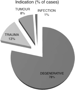
Figure 4. Pie chart showing indications for transpedicular fi xation
(% of cases).
| TABLE 2. Distribution of Pedicle Screws |
| Level |
Number of Screws (%) |
Misplaced Screws (%) |
Grade 0 |
Grade 1 |
Grade 2 |
Grade 3 |
| T4–T8 | 18 (4) | 3 (7.3) | 15 | 0 | 1 (T4), 2 (T7) | 0 |
| T9–T12 | 58 (14) | 4 (9.8) | 54 | 1(T11) | 2 (T9),1 (T10) | 0 |
| L1 | 14 (3) | 1 (2.4) | 13 | 1 | 0 | 0 |
| L2 | 24 (6) | 1 (2.4) | 23 | 1 | 0 | 0 |
| L3 | 63(15) | 10 (24.4) | 53 | 6 | 3 | 1 |
| L4 | 109 (26) | 11 (26.8) | 98 | 7 | 3 | 1 |
| L5 | 100 (24) | 10 (24.4) | 90 | 7 | 3 | 0 |
| S1 | 38 (9) | 1 (2.4) | 37 | 1 | 0 | 0 |
| Total | 424 | 41 (9.7) | 383 | 24 | 15 | 2 |
CT examination provides more information than plain
fi lms, but has obvious limitations. Wiesner15 examined CT
images of screw tracts for cortical wall defects after screw
removal, and reported a low perforation rate of 6.6%.
However, in our study, CT assessment of pedicle placement
was complicated by image artifacts caused by the in vivo
screws. Although clearly a limitation of this study, it could
be thus argued that screw placement in our study may have
greater accuracy than demonstrated by CT examination. A
major limitation of this study is that CT images were examined
in axial sections only. Schizas et al18 showed a lower
incidence of screw perforation in axial images compared
with coronal reconstructions. Thus it could be that the true
incidence of misplacement is higher when CT images are
screened critically including coronal views.
The analysis of the direction of screw misplacements
showed that there were signifi cantly more lateral than medial
pedicle violations at the lumbar levels and half of these could
be attributed to incorrect angle of insertion. This may be
explained by an increasing medial inclination of the pedicle
in the transverse plane from L1 (17 ° –25 ° ) to L5 (26 ° –40 ° ).21
In 1992, Gunzburg et al22 published the results of a radiographic
study in which they found the anatomical pedicle
center lies slightly more lateral than the pedicle shadow.
Initially in the series the starting point for the Jamshidi
needle would be the center of the pedicle on an AP x-ray.
This has the disadvantage that as the Jamshidi needle is
introduced further into the pedicle, the risk of medial pedicle
breach is higher as the starting point of the Jamshidi is potentially
closer to the medial border of the pedicle. The surgeon
altered the technique so that the Jamshidi would be docked
at the very lateral aspect of the pedicle ( Figures 1 A, 2 ), so that
with advancement of the Jamshidi, the risk of medial breach
is reduced. Thus, the accuracy of pedicle screw placement in
this study could potentially be improved by a more lateral
cannulation point with an emphasis on medial inclination.
Prospective analysis of K-wire complications revealed 4
anterior breaches ( Figure 7 ). There is minimal data in the literature
on the potentially devastating complication of vascular and abdominal injury with this technique. The authors documented
all cases and any subsequent complications. There
was a single complication of retroperitoneal hemorrhage and
ileus that improved with conservative measures. The senior
author places all patients with anterior K-wire breach on
broad spectrum antibiotics assuming there has been an intestinal
puncture. It is paramount that the senior surgeon remind
the assistant during the procedure that meticulous care be
taken with stabilizing the K-wire when multiple instruments
and the pedicle screw are placed over the guide K-wire.
The use of fl uoroscopic guidance for screw placement
results in potentially signifi cant radiation exposure to both
the surgeon and patient. Unfortunately, very little data exists
in the literature to help quantify this exposure. Bindal et al23
measured surgeon radiation exposure in minimally invasive
transforaminal lumbar interbody fusion (with similar methods
for fl ouroscopic percutaneous pedicle screw placement),
using dosimeters placed at various locations. Their mean
fl uoroscopy time was 1.69 minutes per case, giving a mean
exposure of 76 mRem to the surgeon’s dominant hand, and
27 mRem to the waist under a lead apron. The mean fl uoroscopy
time in our series ranged from 1.71 minutes per case
for the fi rst 5 single-level cases, to 0.76 minutes per case for
the last 5 single-level cases. The maximum allowed annual
radiation exposure for radiation workers is 5 Rem to the
body and 50 Rem to an extremity.24 Extrapolating the data
from Bindal et al23 , on the basis of the mean fl uoroscopy
time at the end of our series, a surgeon would exceed exposure
limits to the torso after 417 single-level cases and to
the hand after 1471 single-level cases. Of course, multilevel
fusions require correspondingly more fl uoroscopy, and a
surgeon may also perform other interventional procedures
requiring fl uoroscopic guidance, such as vertebroplasty.
Annual dose limits could potentially be exceeded if a large
number of multi-level cases or other fl uoroscopically guided
procedures are performed.
| TABLE 3. Overall View of All Misplaced Pedicles |
| Patient |
Level |
Grade |
Direction of Misplacement |
Screw Angle |
Pedicle Angle |
Δ Angle |
Wrong Angulation |
| 22 | T4 | 2 | Medial | 27 | 7 | 20 | x |
| 22 | T7 | 2 | Lateral | 9 | 11 | –2 | |
| 22 | T7 | 2 | Medial | 24 | 17 | 7 | |
| 85 | T9 | 2 | Medial | 14 | 13 | 1 | |
| 87 | T9 | 2 | Lateral | 2 | 15 | –13 | x |
| 87 | T10 | 2 | Lateral | 13 | 14 | –2 | |
| 29 | 11 | 1 | Lateral | 1 | 12 | –11 | x |
| 37 | L1 | 1 | Lateral | 3 | 15 | –12 | x |
| 32 | L2 | 1 | Lateral | 2 | 13 | –11 | x |
| 2 | L3 | 1 | Medial | 11 | 8 | 3 | |
| 11 | L3 | 1 | Medial | 34 | 30 | 4 |
| 61 | L3 | 2 | Lateral | 8 | 21 | –13 | x |
| 31* | L3 | 3 | Lateral | 3 | 18 | –15 | x |
| 44 | L3 | 1 | Lateral | 10 | 11 | –1 | |
| 46 | L3 | 2 | Medial | 12 | 12 | 0 | |
| 46 | L3 | 2 | Lateral | 10 | 12 | –2 | |
| 65 | L3 | 1 | Lateral | 10 | 12 | –2 | |
| 75 | L3 | 1 | Medial | 1 | 5 | –4 | |
| 82 | L3 | 1 | Lateral | 12 | 14 | –3 | |
| 8 | L4 | 1 | Lateral | 2 | 14 | –12 | x |
| 65 | L4 | 2 | Lateral | 5 | 16 | –11 | x |
| 69 | L4 | 1 | Lateral | 6 | 14 | –8 | |
| 72 | L4 | 1 | Lateral | 12 | 18 | –6 | |
| 28 | L4 | 1 | Medial | 12 | 12 | 1 | |
| 28 | L4 | 1 | Lateral | 4 | 27 | -23 | x |
| 47 | L4 | 1 | Lateral | 17 | 17 | 0 | |
| 49 | L4 | 2 | Lateral | 7 | 18 | –12 | x |
| 54 | L4 | 2 | Lateral | 8 | 15 | –8 | |
| 49 † | L4 | 3 | Lateral | 3 | 23 | –19 | x |
| 80 | L4 | 1 | Lateral | 15 | 15 | 0 | |
| 13 | L5 | 1 | Lateral | 15 | 22 | –6 | |
| 13 | L5 | 2 | Lateral | –3 | 29 | –32 | x |
| 17 | L5 | 1 | Medial | 10 | 17 | –7 | |
| 35 | L5 | 2 | Lateral | 3 | 17 | –14 | x |
| 46 | L5 | 1 | Lateral | 25 | 12 | 13 | x |
| 46 | L5 | 1 | Medial | 23 | 18 | 5 | |
| 54 | L5 | 1 | Lateral | 11 | 25 | –13 | x |
| 65 | L5 | 1 | Lateral | 12 | 32 | –20 | x |
| 77 | L5 | 1 | Lateral | 7 | 21 | –14 | x |
| 86 | L5 | 1 | Lateral | 10 | 10 | 0 | |
| 78 | S1 | 1 | Medial | 8 | 13 | –5 | |
*Pedicle fracture.
†Pedicle fracture + L4 radiculopathy postoperatively. |
Patient exposures in this study were low. The mean
maximum patient skin exposure for the last 5 cases was
44.9 mGy. The threshold for the lowest dose associated with deterministic radiation effects (early transient skin erythema)
is 2000 mGy,25 an order of magnitude higher than
our maximum skin dose.
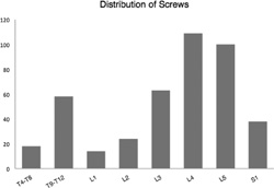
Figure 5. Distribution of all screws with respect to vertebral level.
Both radiation exposure and length of procedure are shortened
with surgeon experience.26 With the exception of assisting
experienced surgeons or attending surgeon cadaver labs
to gain experience, the only alternative is to accept the inherent
learning curve with minimally invasive techniques such as
percutaneous pedicle screw placement. The senior surgeon’s
prospective database reveals a signifi cant reduction in operative
times from the initial 5 single-level percutaneous cases, at
an average of 238 minutes, to 147 minutes with the most recent
5 cases. The senior surgeon also limits exposure by standing 1 meter away from the radiation source whenever an x-ray
is taken where the surgeon does not need to directly handle
an instrument during fl uoroscopy. Although intraoperative
CT-guided percutaneous screw insertion is an alternative to
reduce surgeon radiation exposure, this has the dual disadvantage
of increasing patient exposure with an on-table CT
or additional preoperative CT, and reduced accuracy of screw
insertion.27
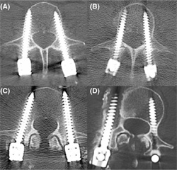
Figure 6. Axial CT images demonstrating grading of screw placement. (A) Grade 0. (B) Grade 1 ( < 2 mm cortical encroachment). (C) Grade 2: ( > 2 mm cortical encroachment). (D) Grade 3 (complication: pedicle fracture).
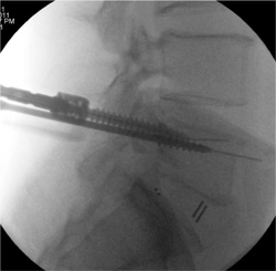
Figure 7. K-Wire complication. Care must be taken with K-wire insertion to ensure that the K-wire is not aggressively advanced into the vertebral body with puncture through the anterior aspect of the vertebra.
This clinical study has shown that percutaneous pedicle
screw insertion in the thoracolumbar spine under fl uoroscopic
guidance is a safe and reliable technique, with a
low misplacement rate and an extremely low rate of complications
compared with the high rates published in the
literature. The drawbacks to this technique include the
inherent learning curve, increased exposure to ionizing
radiation, and increased operating times compared to an
open surgical approach. Once the concepts and techniques
of this procedure have been mastered, however, it offers a
less traumatic, more aesthetic, and equally effective method
for posterolateral fusion.
Key Points
- Percutaneous insertion of cannulated pedicle screws
in the thoracic and lumbar spine is an acceptable
technique with a low complication rate in experienced
hands.
- Insertion of percutaneous pedicle screws is a technically
demanding technique with a steep learning
curve and should be performed with appropriate
training and attention to detail.
- Consistency in the method of screw grading is needed
for comparative studies. We introduce a simple grading
system (Mobbs Raley) for the CT-guided evaluation
of pedicle screw placement.
Acknowledgment
The authors thank Marcus Cremonese, BA, RBI, AIMB
(E-mail: marcus@medicalillustration.com.au; Tel/Fax:
61 + 2 + 9365 5003) for medical illustration (Figures 1 A, B).
References
- France JC , Yaszemski MJ , Lauerman WC , et al. A randomized
prospective study of posterolateral lumbar fusion. Outcomes with
and without pedicle screw instrumentation . Spine (Phila Pa 1976)
1999 ; 24 : 553 – 60 .
- Foley KT , Gupta SK . Percutaneous pedicle screw fi xation of the
lumbar spine: preliminary clinical results . J Neurosurg 2002 ; 97
( 1 Suppl ): 7 – 12 .
- Perez-Cruet MJ , Foley KT , Isaacs RE , et al. Microendoscopic
lumbar discectomy: technical note . Neurosurgery 2002 ; 51
( 5 Suppl) : S129 – 36 .
- Khoo LT , Palmer S , Laich DT , et al. Minimally invasive percutaneous
posterior lumbar interbody fusion . Neurosurgery 2002 ; 51
( 5 Suppl ): S166 – 71 .
- Foley KT , Lefkowitz MA . Advances in minimally invasive spine
surgery . Clin Neurosurg 2002 ; 49 : 499 – 517 .
- Foley KT , Holly LT , Schwender JD . Minimally invasive lumbar
fusion . Spine (Phila Pa 1976) 2003 ; 28 ( 15 Suppl ): S26 – 35 .
- Castro WH , Halm H , Jerosch J , et al. Accuracy of pedicle
screw placement in lumbar vertebrae . Spine (Phila Pa 1976)
1996 ; 21 : 1320 – 4 .
- Farber GL , Place HM , Mazur RA , et al. Accuracy of pedicle screw
placement in lumbar fusions by plain radiographs and computed
tomography . Spine (Phila Pa 1976) 1995 ; 20 : 1494 – 9 .
- Gertzbein SD , Robbins SE . Accuracy of pedicular screw placement
in vivo . Spine (Phila Pa 1976) 1990 ; 15 : 11 – 4 .
- Belmont PJ Jr , Klemme WR , Dhawan A , et al. In vivo accuracy of
thoracic pedicle screws . Spine (Phila Pa 1976) 2001 ; 26 : 2340 – 6 .
- Odgers CJt , Vaccaro AR , Pollack ME , et al. Accuracy of pedicle
screw placement with the assistance of lateral plain radiography . J
Spinal Disord 1996 ; 9 : 334 – 8 .
- Sjostrom L , Jacobsson O , Karlstrom G , et al. CT analysis of pedicles
and screw tracts after implant removal in thoracolumbar fractures
. J Spinal Disord 1993 ; 6 : 225 – 31 .
- Wiesner L , Kothe R , Ruther W . Anatomic evaluation of two different
techniques for the percutaneous insertion of pedicle screws in
the lumbar spine . Spine (Phila Pa 1976) 1999 ; 24 : 1599 – 603 .
- Haaker RG , Eickhoff U , Schopphoff E , et al. Verifi cation of the
position of pedicle screws in lumbar spinal fusion . Eur Spine J
1997 ; 6 : 125 – 8 .
- Wiesner L , Kothe R , Schulitz KP , et al. Clinical evaluation and computed
tomography scan analysis of screw tracts after percutaneous
insertion of pedicle screws in the lumbar spine . Spine (Phila Pa
1976) 2000 ; 25 : 615 – 21 .
- Holly LT , Foley KT . Three-dimensional fl uoroscopy-guided percutaneous
thoracolumbar pedicle screw placement. Technical note . J
Neurosurg 2003 ; 99 ( 3 Suppl ): 324 – 9 .
- Schwender JD , Holly LT , Rouben DP , et al. Minimally invasive
transforaminal lumbar interbody fusion (TLIF): technical feasibility
and initial results . J Spinal Disord Tech 2005 ; 18 ( Suppl 6) : S1 – 6 .
- Schizas C , Michel J , Kosmopoulos V , et al. Computer tomography
assessment of pedicle screw insertion in percutaneous posterior
transpedicular stabilization . Eur Spine J 2007 ; 16 : 613 – 7 .
- Schulze CJ , Munzinger E , Weber U . Clinical relevance of accuracy of
pedicle screw placement. A computed tomographic-supported analysis
. Spine (Phila Pa 1976) 1998 ; 23 : 2215 – 20 ; discussion 20 – 21 .
- Kim YJ , Lenke LG , Cheh G , et al. Evaluation of pedicle screw
placement in the deformed spine using intraoperative plain radiographs:
a comparison with computerized tomography . Spine (Phila
Pa 1976) 2005 ; 30 : 2084 – 8 .
- Ebraheim NA , Rollins JR Jr , Xu R , et al. Projection of the lumbar
pedicle and its morphometric analysis . Spine (Phila Pa 1976)
1996 ; 21 : 1296 – 300 .
- Gunzburg R , Gunzburg J , Wagner J , et al. Radiologic interpretation
of lumbar vertebral rotation . Spine (Phila Pa 1976) 1992 ; 16 : 660 – 4 .
- Bindal RK , Glaze S , Ognoskie M , Tunner V , Malone R , Ghosh
S . Surgeon and patient radiation exposure in minimally invasive
transforaminal lumbar interbody fusion . J Neurosurg Spine
2008 ; 9 : 570 – 3 .
- ARPANSA . Recommendations for Limiting Exposure to Ionizing
Radiation (1995) and National Standard for Limiting Occupational
Exposure to Ionizing Radiation (republished 2002) . National
Occupational Health and Safety Commission , 1995 . http://www.
arpansa.gov.au/pubs/rps/rps1.pdf . Accessed January 2011.
- Synowitz M , Kiwit J . Surgeon’s radiation exposure during percutaneous
vertebroplasty . J Neurosurg Spine 2006 ; 4 : 106 – 9 .
- Gonzalvo A , Fitt G , Liew S , et al. The learning curve of pedicle
screw placement: how many screws are enough ? Spine (Phila Pa
1976) . 2009 ; 34 : E761 – 5 .
- Mobbs RJ , Sivabalan P , Li J . Technique, challenges and indications for
percutaneous pedicle screw fi xation . J Clin Neurosci 2011 ; 18 : 741 – 9 .
 CT Scan Analysis of Percutaneous Fusion CT Scan Analysis of Percutaneous Fusion
You will need the Adobe Reader to view and print the above documents. 
|